রবিবার, ৫ জুন, ২০১১

Concrete curing

Methods of Curing
Several techniques are adopted for curing. They may be grouped under the following four types:
(i) Water curing
(ii) Membrane curing
(iii) Temperature curing
(iv) Miscellaneous curing

Water curing  

The methods using water for promotion of hydration and absorption of heat of hydration may be called as water curing methods. These are the excellent methods of curing. Water curing can be done by the following ways:
(1) Spraying
(2) Wet covering
(3) Ponding
(4) Immersion.
Spraying of water at regular intervals is done for curing vertical surfaces of concrete. This is not a good technique, since the surface of concrete is not taken care of continuously.


                                             Figure 1: Concrete curing.
Wet covering is provided using jute bags, saw dust, wet sand, etc. on the surface of the concrete.
For curing surfaces like slab, ponding technique is used. It consists of providing little earthen bands on the surface to see if a water pond of about a few millimeter depth can be retained. This is the best method of curing the slabs.
For curing precast concrete elements, the best method is to immerse the units in curing tanks.

Membrane curing

Curing does not mean only the application of water. It means maintaining suitable conditions for the promotion of uninterrupted and progressive hydration. If water is available in restricted measures, one can think of sealing the concrete surface using suitable sealing compounds for one or two days.


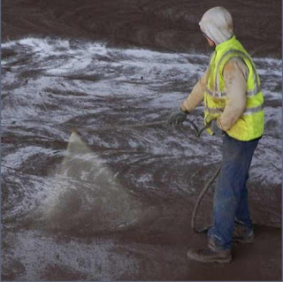
Figure 2: reinforcement.

Figure 3: Placing of concrete.
Figure 4: Finishing of concrete.
Figure 5: Spraying of curing membrane.
                                                      
Bituminous compounds and rubber compounds are some of the surface sealing compounds applied by spraying under pressure. Polythene or polyester films, water proof papers, etc. are also used as surface sealing materials. Two or three coats may be necessary for an effective sealing

Temperature Curing

If wetness is maintained and at the same time temperature is increased, the hydration process accelerates and within a short time the concrete gains sufficient strength. The following techniques may be employed:
Steam curing at ordinary pressure
Steam curing at high pressure
Curing by infra-red radiation and electric curing
Miscellaneous methods  
Calcium chloride as a salt has high affinity for moisture. Hence, if calcium chloride is applied to the surface, it retains the moisture and helps in curing.
Sealing of the form work is another method of preventing evaporation of moisture.


Physical Properties Of Cement


The physical properties prescribed are about
(a) setting time
(b) strength
(c) soundness
(d) fineness of grinding
IS 269-1975 prescribes the requirement and the standard procedure to determine the above properties.
Table shows the physical properties prescribed for ordinary portland cement.
Table: Requirement of physical properties of cement
Physical property
Standard prescribed
(a) Setting time
            (i) Initial
            (ii) Final
 
(b) Compressive strength of mortar with standard sand
            (i) After 3 days ± 1 hour
            (ii) After 6 days ± 2 hours
 
            Tensile strength
            (i) After 3 days
            (ii) After 7 days
 
Not less than 30 min
Not more than 600 min


Not less than 16 N/mm2
Not less than 22 N/mm2
 
 
Not less than 2.0 N/mm2
Not less than 2.5 N/mm2
(c) Soundness
            (i) By Le-chatelier method
            (ii) By autoclave method
 
(d) Fineness
            (i) Residue by weight on IS 90 micron sieve
            (ii) Specific surface by air permeability method
 
Expansion not more than 10 mm
Expansion not more than 0.5%
 
 Not more than 10%
 
Not less than 2250

Cement Mortar


Cement mortar is an intimate mixture of cement and sand mixed with sufficient water to produce a plastic mass. The amount of water will vary according to the proportion and condition of the sand, and had best be determined independently in each case. Sand is used both for the sake of economy and to avoid cracks due to shrinkage of cement in setting.
Properties of cement mortar are:
   1. When water is added to an intimate dry mixtures of cement and sand, hydration of cement starts and it binds sand particles and the surrounding surfaces of masonry and concrete.
   2. The strength of mortar depends upon the proportion of cement and sand.

PROPORTIONING Of CEMENT MORTAR

Strong and workable mortar is obtained if the ratio of cement and sand is between 1:3 to 1:6. However, the occasional use of 1:8. ratio is permitted. Strength and workability improve with the increase in cement content (rich mixes). However, mortars richer than 1:3 proportion are not used because of high shrinkage and no appreciable gain in strength. In case of lean mixtures, voids in the sand are not impervious.
Proportions recommended for various workers are as follows:
1.
Masonary works
1:6 to 1:8
2.
Plastering masonry
1:3 to 1:4
3.
Plastering concrete surface
1:3
4.
Pointing
1:2 to 1:3

USES OF CEMENT MORTAR

(1) To bind masonry units like stones, bricks and hollow cement blocks.
(2) To give impervious surface to roof slab and walls (plastering).
(3)To give neat finishing to concrete works.
(4) For pointing masonry joints.
(5) For preparing hollow blocks.
(6) As a filler material in ferro-cement works.

Cantilever Retaining Walls


Cantilever retaining walls are constructed from reinforced concrete. A relatively thin stem and a base slab are their special characteristics. The base is also divided into two parts, the heel and toe. The heel is that part of the base which is under the backfill. The toe is the other part of the base.

These walls utilize much less concrete than monolithic gravity walls, but they demand more design and careful construction. They are generally economical up to about 25 ft. in height. The fact that they can be precast in a factory or even formed on site makes them a preferred option.

The design of these retaining walls is affected by:
i.    Wall height
ii.    Soil type
iii.    Sloping land below and/ or above the retaining wall
iv.    Loads above as well as behind the retaining wall

Engineering mechanics Math


Example:
Two rough planes inclined at 30° and 60° to horizontal are placed back to back as shown in Fig.. Two blocks weighing 60 and 120 N respectively are placed on the faces inclined at 30° and 60' respectively and are connected by a string running parallel to planes and passing over a frictionless pulley. If the coefficient of friction between planes and blocks is 0.3, find the resulting acceleration and tension in the string?
Solution:solved examples d alamberts principle 2.jpg

Let the assembly move down the 60° plane by an acceleration 'a' m/sec2. Free body diagrams of 120 N and 60 N blocks along with inertia forces are shown in Figs. (b) and (c) respectively.
Consider the block weighing 120 N:
Forces normal to the plane = 0 gives
N1 = 120 cos 60° = 60 N                                                                 (i)
From the law of friction
 
F1 = mN1, = 0.3 × 60 = 18 N
 
S Forces parallel to the plane = 0 gives                                                   (ii)
T + 120 / 9.81 a + F1 – 120sin60° = 0 9.81
T + 120/ 9.81 120 sin 60°– F1
 
= 120 sin 60°–18
 
= 85.923                                                                     (iii)
 
Now consider 60 N block:
 
S Forces normal to plane = 0 gives
 
N2 = 60 cos 30° = 51.926N                                                            (iv)
 
From the law of friction,
 
F2 = mN2 = 0.3 × 51.926 = 15.588 N                                             (v)
 
S Forces parallel to 30° plane = 0
 
60 sin 30° + F2 + 60 / 9.81 a – T = 0
 
60 / 9.81 a – T = –60 sin 30° – 15.588,                             since F2 = 15.588 N
 
\ 60 / 9.81 a – T = –45.588
 
Adding eqns. (iii) and (vi), we get
 
180 / 9.81 a = 85.923 – 45.588 = 40.335
 
a = 2.19825 m/sec2
 
Substituting the value of acceleration 'a' in eqn. (iii), we get
 
7 + 120 / 9.81 × 2.19825 = 85.923 9.81
 
T = 59.033 N

শনিবার, ৪ জুন, ২০১১


Structural steel is steel construction material, a profile, formed with a specific shape or cross section and certain standards of chemical composition and mechanical properties. Structural steel shape, size, composition, strength, storage, etc., is regulated in most industrialized countries.
Structural steel members, such as I-beams, have high second moments of area, which allow them to be very stiff in respect to their cross-sectional area.

Common structural shapes
In most developed countries, the shapes available are set out in published standards, although a number of specialist and proprietary cross sections are also available.
  • I-beam (I-shaped cross-section - in Britain these include Universal Beams (UB) and Universal Columns (UC); in Europe it includes the IPE, HE, HL, HD and other sections; in the US it includes Wide Flange (WF) and H sections)

Figure 1: Typical cross-sections of I-beams.

  • Z-Shape (half a flange in opposite directions)
Figure. 3: Z sections.
 
Figure 2: Hollow section.

  • Angle (L-shaped cross-section)
Figure 3: Angle section.

  • Channel ( [-shaped cross-section)
Figure 4: channel section.

  • Tee (T-shaped cross-section)

Figure 5: T section.

While many sections are made by hot or cold rolling, others are made by welding together flat or bent plates (for example, the largest circular hollow sections are made from flat plate bent into a circle and seam-welded)